|
|
Application module:
State based behaviour |
ISO/TS 10303-1371:2011-10(E)
© ISO
|
Annex F
(informative)
Application module implementation and usage guide
F.1 Introduction
State Based Behaviour is a representation of what a system is to do based on descriptions of
its relevant characteristics or conditions at particular intervals. What a thing does can be
described by citing a set of significant conditions. What a car does can be described by a set of
conditions and how one condition proceeds to the next. The conditions might be: off, running,
stopped, accelerating, cruising, decelerating, etc. Something happens, an event, to cause
change from one condition to the next.
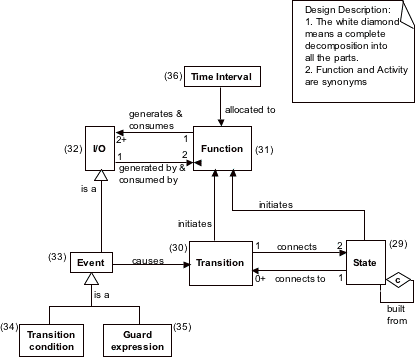
Figure F.1 — Definitions concerning state based behaviour - SE Handbook Chapter 33 Figure 6
Figure F.1 and
the (numbered) definitions below provide the relationships for the state based
behaviour representation problem.
An engineering thing is that for which observable, measurable, and reproducible properties or
attributes can be obtained.
State (29) is the relevant configuration, attributes, condition, or information content
characteristics or conditions of an engineering thing. Persons and things can be described in
terms of their past, present, and future conditions.
Transition (30) is the connection between one condition of an engineering thing and a
different condition of that engineering thing. A Transition is the concept applied to
getting from one State or set of conditions to another. In the digital approximation this is
assumed to take zero time. In real physical things this is an approximation because going from
one condition to another always takes time even thought the time may be very short. Each
transition connects an initial state to a final state. A state can exist that is unchanging over
the period of interest and hence has no transitions. Mathematical representations of state and
transition make use of directed graphs.
Function (31) is a transformation that consumes one set of engineering things and generates or
transforms them into another set of engineering things.
I/O (32) is the output from one Function and an input to another Function.
Event (33) is the subset of I/O that causes a Transition from one State to another. Some, but not all,
I/O result in a Transition because they represent a change in the condition of an engineering thing.
Transition_condition (34)is a condition that would need to be fulfilled to enable the Transition.
Some of the outputs of a Function are a special kind of Event that must necessarily be present
(produced by the function) for the Transition to take place.
Guard_expression (35) is a condition that must be true for the Transition to be triggered. Some of
the outputs of a function are a special kind of event that must necessarily be true for the
transition to take place.
Time_interval (36) is a period of time during which a Function produces its I/O. In some disciplines
the transitions are found to be fast enough that they can be considered to be instantaneous.
Transformation of inputs into outputs takes a finite amount of time. The Time_intervals can be
assigned to a complex set of functions and then the time line for the behaviour can be calculated
from the model. In this manner an overall required time response can be calculated from a
design behaviour model. That prediction can then be verified by measurement when the system is
built.
F.2 Assigning Behaviour to a State Definition
There are several relationships possible between various representations or definitions of behaviour specified in
this part of ISO 10303. For the purpose of specifying the behaviour that occurs while in a state or when entering or exiting
a state, the particular approach to be used depends on the usage scenario or state machine tool capability.
The Behaviour_description_association concept is used in all cases. This allows for a single, consistent approach.
This is also the concept used to relate a behaviour model representation to the behaviour view is defined. The possibilities
follow.
- In the case that the behaviour management capabilites are used, then the behaviour model is assigned to the State_definition.
- In the case that the behaviour is defined by a simple name, the behaviour is represented as an Activity_method and that is
assigned to the State_definition. An Activity_method_assignment is not used for this purpose for the
sake of consistency with the assignment of any kind of definition of behaviour.
- In the case that the behaviour also has a state definition itself, then one State_definition is assigned to the other.
A State_definition_relationship is not used for this purpose for the sake of consistency with the assignment of
any kind of definition of behaviour.
© ISO 2011 — All rights reserved