|
|
Application module:
AP233 systems engineering |
ISO/TS 10303-433:2011-10(E)
© ISO
|
ISO 10303 is an International Standard for the computer-interpretable
representation of product information and for the exchange of product data.
The objective is to provide a neutral mechanism capable of describing
products throughout their life cycle. This mechanism is suitable not only
for neutral file exchange, but also as a basis for implementing and
sharing product databases, and as a basis
for retention and archiving.
This part of ISO 10303 specifies an application module for the
representation of the variety of general model classifications used to
support model based systems engineering. This includes all models used to
characterize the physical structure and its behaviour and the full range of
models used to support systems engineering trade studies.
This module ISO/TS 10303-433 Application module: AP233 systems engineering
is the top level application module for AP233. It brings
together the system modelling capabilities and the program management
capabilities. As such, the variety of modelling paradigms used to
represent the physical and functional system and capabilities used
to support associated verification, validation and trade studies as well
as the program management activities of systems engineering.
NOTE
The following overview text What systems engineering is repeats the introductory
text of ISO 10303-233 Application protocol: Systems engineering.
Additional overview material and an Ap233 documentation guide to all relevant
ISO 10303 application modules is provided therein.
What systems engineering is
Systems Engineering is an interdisciplinary collaborative approach to derive, evolve,
and verify a life cycle balanced system solution that satisfies customer expectations and
meets public acceptability. (IEEE 1220-1984)
Systems Engineering is an interdisciplinary approach and means to enable the realization
of successful systems. It focuses on defining customer needs and required functionality early
in the development cycle, documenting requirements, then proceeding with design synthesis and
system validation while considering the complete problem.
The complete problem spans:
- stakeholder needs;
- requirements;
- the enterprise and competitors;
- concept;
- design;
- design optimization by trade studies;
- design validation and verification;
- manufacture;
- product validation and verification;
- test;
- maintenance;
- operations;
- performance;
- disposal;
- training and support;
- cost and schedule;
- program management.
Systems Engineering integrates all the disciplines and specialty groups into a team effort
forming a structured development process that proceeds from concept to production to operation.
Systems Engineering considers both the business and the technical needs of all customers with
the goal of providing a quality product that meets the user needs. (Definition of the
International Council on Systems Engineering (INCOSE))
Systems Engineering makes extensive use of specification of all interfaces, performance
analysis, and trade studies to ensure that the system is near optimal for and will be accepted
by stakeholders and the marketplace. It is applicable to anything for which a well-defined
boundary can be established whether mechanical, electrical, electronic, information, chemical,
biological, social or organizational.
What AP233 is
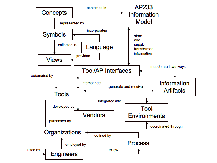
AP233 is an information model that captures the concepts used in Systems Engineering, as
Figure 1 shows.
These concepts may be represented by a variety of symbols and each set of such
symbols can be combined into an number of different views. A particular set of symbols and views
constitutes a language. Tools automate the use of such a language to represent and model systems.
For any language a number of different tools may exist and they may not be able to exchange data
even using the same language unless they have compatible schema for storing that language. Thus a
single set of concepts results in a plethora of languages and tools.
Figure 1 — AP233 Information model
The tools are used by engineers. Frequently it is the organization that establishes the process,
a specification of the views and development order that must be followed, that the engineers
shall follow. Two organizations using the same tool may or may not use equivalent views in doing
their work.
In general, there is no single tool that can support all the work that must be done so the
tools are most efficient when put in an environment that enables them to exchange the information
artifacts that the engineers produce using the tools. Often, different tools incorporated in a
single environment cannot exchange information. Very often, the organizations in a supply chain
or working together on a single project as a consortium will have different environments
incorporating different sets of tools. Yet all members of the supply chain or consortium need
to efficiently share data rigorously and at low cost.
The application protocol, like AP233 for Systems Engineering, provides a solution to this
problem. Each tool needs an interface that interconnects the tool with the AP. The interface
transforms the data artifacts from the tool for correct storage in the AP and transforms data
supplied by the AP for use by the tool.
In this way AP233 supports information exchange among organizations, even though their
environments contain different tools. AP233 is the glue for organizations working together
in a consortium or a supply chain.
What Ap233 contains
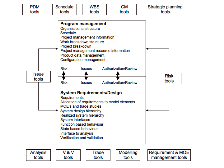
Figure 2 shows.
shows the basic capabilities of AP233. It is divided into two main parts, Program
Management and System Requirements/Design. Major capabilities are listed in each box. The
relevant kinds of tools that are applicable surround each box. The two main parts of the work
are interconnected by risk analysis, issue resolution, and management authorization and review.
Where these capabilities share concepts, i.e. where they are semantically equivalent, there can
be exchange of information artifacts among any of the tools through the tool interfaces and the
AP233 information model.
Figure 2 — AP233 content and associated tools
The same transfer is possible where there is semantic identity with downstream design,
manufacture, test, and maintenance tools. There are many ISO 10303 Application Protocols
(APs) for a variety of industrial businesses such as, geometry, circuit board and chip
development, shipbuilding, building construction, furniture design and manufacture, maintenance.
A large number of different tools are used by these businesses and interface through their
own APs. All of these APs have been made modular and share, as much as possible, the same modules
This approach is vital for connecting systems engineering tools to downstream tools and it makes
possible the use of AP233 as an integrating AP across all the others.
The shared modularity has also required that the AP233 modules use naming conventions that
were developed a decade or more ago by developers in other disciplines. The consequence is that
AP233 contains names in the detailed EXPRESS code that will seem foreign to practicing systems
engineers. It also means that many modules will use a different common module for widely needed
representation of concepts like number or a weighting factor. Thus the reader who looks at a
particular module may not see there an entity that he knows belongs there because it resides
in a shared module and is connected to the module he is reading. Efficient use of the EXPRESS
language also means that the connection to the common module may go through a chain of classes
and subclasses; it may be very indirect for the reader.
For the reasons above, this introduction does not attempt to show the reader the details of
the EXPRESS code. Rather this introduction attempts to:
- describe AP233 as a container of concepts shared by tools;
- list number of the AP233 capabilities;
- show kinds of tools that can interface with one another through AP233;
- show the major mappings of capabilities onto the modules that constitute the information module.
Those who wish to investigate the modules in detail can use this Introduction as a guide to
that adventure.
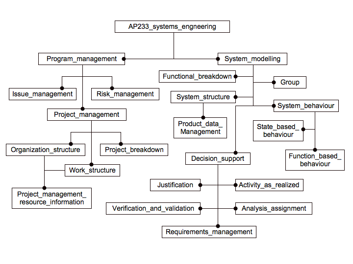
Figure 3 shows.
shows a top-level view of the module hierarchy. It is important to be
aware that the boxes under a higher box do not necessarily completely compose it. Rather there
may be additional things in the box above. This is not intuitive to those accustomed to hardware
development, but it is a result of the software languages.
Figure 3 — Top-level hierarchy of AP233 modules
The capabilities of Figure 2
map into modules of Figure 3
as identified below. Be
aware that these are not leaf cell modules. There may be structure below them, and they may
connect to modules above and below through type extensions. This makes reading the code or
the graphic EXPRESS-G diagrams difficult, but it is the nature of the language.
Program management capabilities
System requirements and design capabilities
This introduction continues in Annex F
with a series of module connectivity concept maps.
These attempt to bridge the gap between what the system engineer wants to see for review purposes and how the
information modelling experts enabled AP233.
This
second
edition of this part of ISO 10303 incorporates the modifications to the
first
edition listed in Annex G.2.
Clause 1 defines the scope of the
application module and summarizes the functionality and data covered.
Clause 3 lists the words defined in
this part of ISO 10303 and gives pointers to words defined elsewhere.
The information requirements of the application are specified in Clause
4 using terminology appropriate to
the application.
A graphical representation of the information requirements, referred to
as the application reference model, is given in Annex
C.
Resource constructs are interpreted to meet the information
requirements.
This interpretation produces the module interpreted model (MIM).
This interpretation, given in 5.1,
shows the correspondence between the information requirements and the
MIM. The short listing of the MIM specifies the interface to the
resources and is given in 5.2.
A graphical representation of the short listing of the MIM is given
in Annex D.
In ISO 10303, the same English language words can be
used to refer to an object in the real world or concept, and as the
name of an EXPRESS data type that represents this object or concept.
The following typographical convention is used to distinguish between
these. If a word or phrase occurs in the same typeface as narrative
text, the referent is the object or concept. If the word or phrase
occurs in a bold typeface or as a hyperlink, the referent is the
EXPRESS data type.
The name of an EXPRESS data type can be used to refer to the data type
itself, or to an instance of the data type. The distinction between
these uses is normally clear from the context. If there is a likelihood
of ambiguity, either the phrase "entity data type" or "instance(s) of" is
included in the text.
Double quotation marks " " denote quoted text. Single quotation marks ' '
denote particular text string values.
© ISO 2011 — All rights reserved


